
NEWS & INSIGHTS
Stay Informed. Keep Moving.
Related Posts
- ▶ First vs. Second Generation Wheel Hub Bearings: Installation Differences
- ▶ Second Generation Wheel Hub Bearings: Design and Mounting Explained
- ▶ Automotive AC Compressor Bearings: How Heat and Speed Affect Service Life
- ▶ First Generation Wheel Hub Bearings: Design and Installation Basics
- ▶ Why Do Wheel Hub Bearings Fail? Common Causes and Diagnostic Signs
- ▶ Selecting Tapered Roller Bearings for Combined Radial and Axial Loads
Send Us A Message
Second Generation Wheel Hub Bearings: Design and Mounting Explained
Second Generation Wheel Hub Bearings combine a double-row bearing with an integrated flange. The flange provides a mounting interface at the wheel end, while the bearing supports radial loads and axial loads from both directions. Compared with an arrangement assembled from separate bearings and mounting parts, the unit reduces the number of components handled during installation.
The bearing is generally supplied as a preassembled, sealed unit. Its internal geometry and clearance are established during manufacture, so it is not normally adjusted like a conventional pair of tapered roller bearings. The exact flange arrangement, retention method and service procedure vary with the vehicle and bearing design.
What the integrated flange does
In a common configuration, the flange is formed on the outer ring and fastens the bearing unit to the steering knuckle or axle housing. The inner rings support a separate hub or shaft. Other configurations use a flange on the rotating side, so the appearance of a flange alone does not establish which part is stationary or how the unit is retained.
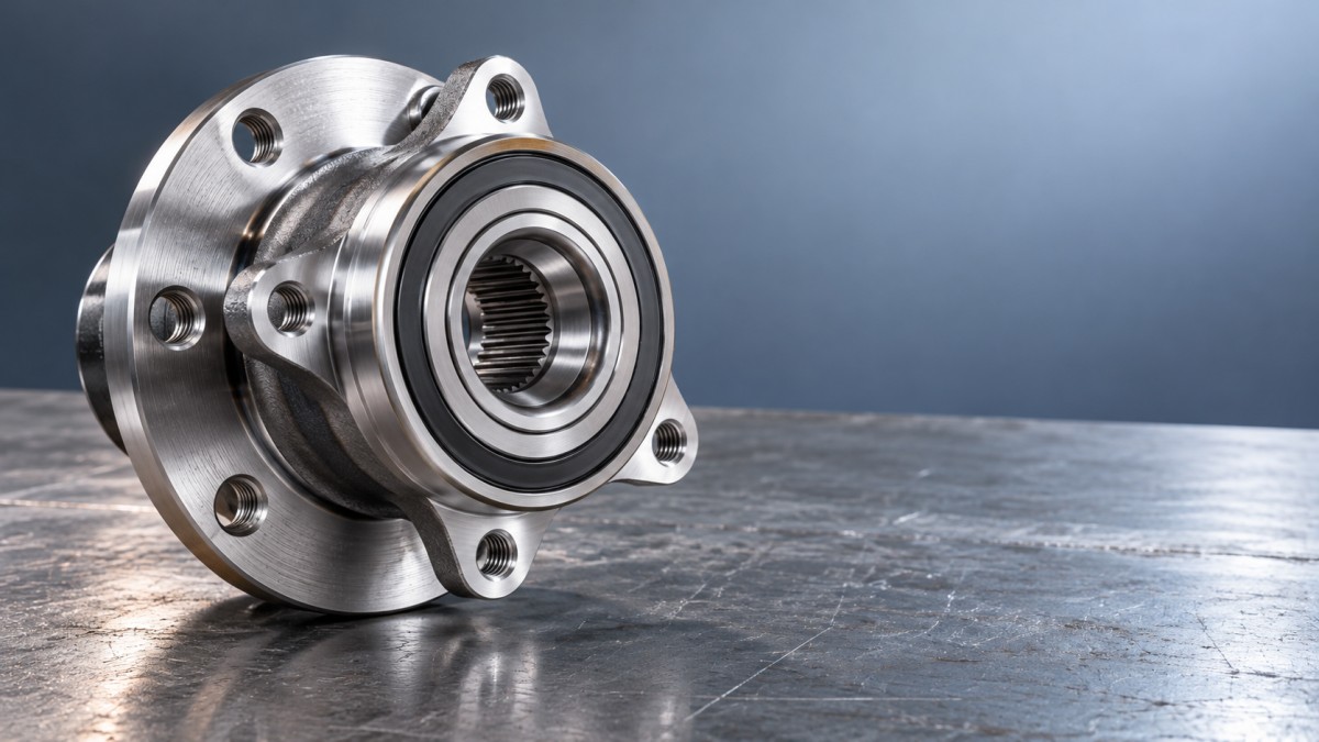
The flange locates the unit and transfers wheel-end loads into the surrounding structure. Its bolt pattern is only one part of the fit: the register diameter, flange face, bearing width and position relative to the hub must also match. Two units with similar bolt spacing can place the wheel or brake components differently if their offsets or locating surfaces differ.
Seals retain lubricant and limit the entry of water and contaminants. Some designs also incorporate an encoder for a wheel-speed sensor. When an encoder is present, its position and orientation must match the vehicle's sensor arrangement; a bearing that fits mechanically can still give an incorrect or missing speed signal.
Mounting loads must follow the supported ring
Installation begins with clean, undamaged mating surfaces. Corrosion, burrs or debris on the register or flange face can prevent the unit from seating squarely. A tilted bearing can distort the mounting interface and make bolt tightening misleading: bolts may feel tight before the flange is fully seated.
Where a press fit is specified, the pressing tool must bear against the ring being fitted. Force applied to the opposite ring passes through the rolling elements and can mark their raceways. For example, when pressing an outer ring into a housing, support and press on that outer ring; when fitting a hub into an inner ring, support the appropriate inner ring. The exact setup must follow the vehicle and bearing manufacturer's procedure.
Do not press on the seal, encoder surface or a dust shield. Avoid hammering the unit into position: impact loads are difficult to control and can damage surfaces that are not visible after assembly. If insertion force is unexpectedly high, stop and inspect the fit and alignment rather than forcing the parts together.
Fastening and final seating
A flanged unit is commonly secured with bolts, but the axle nut or other shaft retention hardware can also be part of the bearing's load path. Tightening sequences, torque values, angle procedures and replacement requirements are application-specific. Use the specified fasteners and follow the vehicle service instructions; a generic torque figure is not a reliable substitute.
Before reassembly is complete, confirm that the flange sits flush against its mating face and that the hub turns without binding. A rough feel after installation does not by itself identify the cause: contamination, a misaligned seat, damage during pressing or contact with an adjacent component can produce similar symptoms. Investigating the seating and installation process is more useful than assuming the seal or lubricant is responsible.
Where a magnetic encoder is fitted, protect its surface from metal debris and verify that the sensor faces the correct side. A missing wheel-speed signal after replacement can result from reversed orientation, contamination or sensor damage even when the bearing rotates freely.
- Last One:No more articles
- Next Article:No more articles