
NEWS & INSIGHTS
Stay Informed. Keep Moving.
Related Posts
- ▶ First vs. Second Generation Wheel Hub Bearings: Installation Differences
- ▶ Second Generation Wheel Hub Bearings: Design and Mounting Explained
- ▶ Automotive AC Compressor Bearings: How Heat and Speed Affect Service Life
- ▶ First Generation Wheel Hub Bearings: Design and Installation Basics
- ▶ Why Do Wheel Hub Bearings Fail? Common Causes and Diagnostic Signs
- ▶ Selecting Tapered Roller Bearings for Combined Radial and Axial Loads
Send Us A Message
First vs. Second Generation Wheel Hub Bearings: Installation Differences
First-generation wheel hub bearings are generally separate bearing units pressed into a steering knuckle and fitted around a separate hub. Second-generation designs incorporate a flange into the bearing assembly, changing how the hub interface is installed and supported. The practical distinction is not simply whether a press is needed: it is where installation forces must be applied and which components establish the finished assembly’s position.
Generation labels are useful shorthand, but they do not replace a vehicle-specific service procedure. A second-generation bearing may still require pressing into the knuckle, and flange geometry, retention methods and drive arrangements vary by application.
How the bearing and hub are installed
A typical first-generation arrangement uses a sealed, double-row bearing with separate inner and outer rings. The outer ring is installed in the knuckle bore, often against a shoulder and secured by a retaining ring. The hub is then pressed into the bearing’s inner ring. Depending on the vehicle, removal may involve extracting the hub first, leaving an inner-ring section on it, and then pressing the bearing out of the knuckle.
With many Second Generation Wheel Hub Bearings, the wheel-mounting flange is integrated with the bearing unit. This reduces the number of separate hub-bearing interfaces, but does not necessarily make the assembly a bolt-on replacement. Some designs are retained in the knuckle by a press fit and retaining ring; the exact arrangement must be confirmed from the part and vehicle documentation.
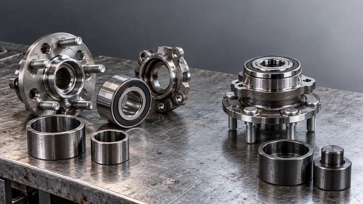
The distinction matters when assessing service equipment. A press fixture suitable for a separate first-generation bearing and hub may not locate or support an integrated-flange unit correctly. Tool clearance around the flange and access to the retaining feature can be as important as the bearing’s nominal diameter.
Controlling the installation load path
Press force should be applied to the ring being fitted, without transmitting the load through the rolling elements. When a bearing’s outer ring is pressed into a knuckle, the press adapter should bear on the appropriate outer-ring surface. If the separate hub is then pressed into a first-generation bearing, the relevant inner ring must be supported as specified by the bearing or vehicle manufacturer.
Pressing on the wrong ring can force the rolling elements against their raceways. Damage may not be visible during assembly, but can shorten bearing life or cause noise after installation. Seals, encoder components and other vulnerable surfaces should not be used as press contact points.
For an integrated-flange unit, the approved tool must match its design and apply force through the specified surfaces. The presence of a flange alone does not establish where force may safely be applied. Removal loads also deserve attention: pressing an assembly apart can damage bearing components, so removed bearings should not be assumed reusable.
Fit, retention and orientation checks
Before installation, inspect the knuckle bore and shoulders for corrosion, scoring, burrs or deformation. A damaged bore can prevent full seating or compromise the intended interference fit even when the replacement bearing has the correct stated dimensions. Clean the mating surfaces using the method specified by the vehicle or bearing manufacturer; do not assume that lubricant, adhesive or abrasive reconditioning is acceptable.
Check that the bearing seats against its locating shoulder and that any retaining ring or other locking feature engages fully. A retaining ring fitted into a partially obstructed groove may appear installed without actually securing the bearing. On first-generation assemblies, the hub’s seating and the condition of any reused hub surface are also important: a damaged hub journal can undermine a correctly installed new bearing.
Orientation can be critical on either generation. Some sealed bearings incorporate a magnetic encoder for a wheel-speed sensor on one side. Installing the bearing backwards can prevent a correct sensor signal even though the mechanical fit appears sound. Identify the encoder side using the manufacturer’s instructions and protect it from contamination and tool contact.
Fastener torque is not a substitute for correct pressing
Where the vehicle uses a driven hub, the axle nut or bolt may be essential to clamping the bearing’s inner components. Follow the specified tightening sequence, torque and any angle requirement for the exact application; use a new fastener where required. Incorrect clamping can affect bearing operation, while using a generic torque value risks damage or inadequate retention.
Do not use the axle fastener to draw an improperly seated bearing or hub into position unless the vehicle procedure explicitly requires it. Press installation and final fastener tightening perform different functions. Before the vehicle is returned to service, verify seating and retention, check rotation and wheel-speed sensor operation as applicable, and complete any checks prescribed by the vehicle manufacturer.
For interchangeability, compare more than outside diameter and width. The relevant specification includes flange configuration, bearing orientation, retaining features, encoder arrangement, hub or axle interface and the installation method. Two units with similar dimensions can require different tooling or produce an incorrect assembly if those interfaces do not match.
- Last One:No more articles
- Next Article:No more articles